1. Define what makes it the same product
A similar color does not prove that a product has stayed the same. If a mug turns halfway around and its handle suddenly connects to the lid, attractive lighting cannot rescue the structure. This fictional exercise uses a matte blue insulated mug with a cylindrical body, one closed handle, a flat lid with one drinking opening and a small square mark on the front. Lock the parts and their connections before planning camera angles and motion, then review against structural evidence. Dimensions in this exercise are design choices, not specifications for an actual product. For sales imagery, use approved physical samples, engineering drawings or photographs, and ask the product owner which details must remain exact. A generated image is not evidence of the real product’s construction.
2. Turn references into a structural checklist
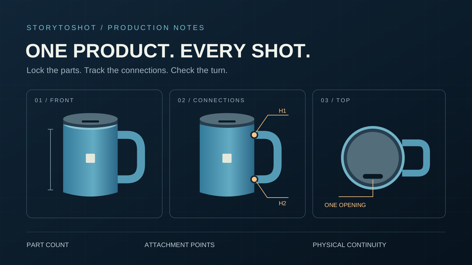
Collect front, side, rear and top references of the same product version, labeling orientation and revision. Record five things: part count, attachment points, relative proportions, opening direction and fixed marks. For this exercise, the body is about 1.6 times as tall as its diameter. Both ends of the handle attach to the body, the drinking opening sits near the front edge of the lid, and the square mark stays near the center of the front surface. Different views must explain the same relationships. Do not mix old packaging images with a redesigned sample, or treat photographs taken with different lenses as precise dimensional drawings. Mark unclear areas as unknown and obtain another view. Asking a model to invent hidden details can carry an unapproved design into every later shot.Keep original reference filenames and label critical connections, for example H1 for the upper attachment and H2 for the lower one. Refer to these labels in review notes so that a bend in the handle is not mistaken for a moved attachment. Compare proportions in comparable views; do not divide a top view’s projected height by a frontal width.
3. Give four shots distinct demonstration jobs
List what viewers need to confirm before drawing the shots. Shot A is a locked frontal medium view establishing silhouette, color and the square mark. Shot B is a front-side close view showing both handle attachments. Shot C looks down at the lid to establish the drinking opening. Shot D returns to the front as a hand grips the handle and lifts the mug slightly off the table. Give each shot one main piece of evidence and enough time to read it. Shot B does not require a full revolution, and shot C does not need the lid to open at the same time. Copy this row format: “shot ID, structure that must be visible, permitted motion, fixed features, pass condition.” If one shot fails, the plan identifies the missing view instead of sending the entire advertisement back into generation.
4. Describe structure before motion and lighting
Keep a shared structural description in every shot brief, then add the changes for that shot. For B, try: “The same matte blue cylindrical mug. The upper and lower ends of its single closed handle attach to the body. The flat lid has one drinking opening. Front-side close view, stationary mug, locked camera, soft side light revealing both attachment points.” If a small turn is needed, specify its direction and stopping pose separately and mark the endpoint on a reference. Repeating “perfect consistency, no deformation” does not replace a description of the connections. Tools differ in their support for reference images, motion instructions and constraints. This is a production brief, not a promise of model compliance. Check what inputs the interface accepts, then judge the result against the same acceptance criteria.
5. Separate perspective, occlusion and deformation
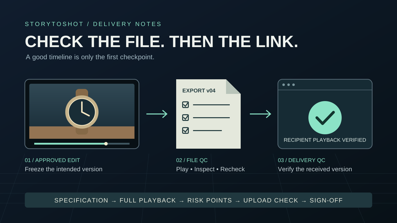
A circular rim appears elliptical from an oblique angle, and the body can hide a handle as it turns away. Neither change is automatically an error. Track how the same part enters or leaves view: the handle should progressively pass behind the body’s edge rather than disappear in an unobstructed area. An opening may narrow with perspective but should not become two holes. Watch at normal speed first, then inspect the beginning, ending and frames around occlusion. Step through the suspicious interval when necessary. A still-image overlay is only an aid; different cameras, perspectives and object poses can create misleading differences. Ask whether one physical object could explain the change, rather than requiring a pixel-identical silhouette in every frame.
6. Use lighting to reveal the structure
Highlights can make a product attractive while concealing seams and edges. Validate the structure under soft, readable lighting before creating a more atmospheric version, and review each version independently. A moving bright band on the lid does not necessarily mean an extra layer, but a persistent physical edge beneath it calls for a thickness check. The square mark should travel with the body surface, not slide with the highlight. For logos, scales and model numbers that must be exact, consider a controlled compositing workflow and verify perspective, occlusion and tracking. Placing a flat image over the shot is not enough. If those elements cannot stay attached convincingly, approved photography or 3D product assets offer more direct control.
7. Give every generation a specific acceptance decision
Avoid “close enough” as a review result. Record evidence such as: “B02: lower handle attachment separates from the body during the turn; structure failed. B03: both attachments remain visible and connected; structure passed, edit continuity still pending.” Separate severity levels. Added or missing parts, incorrect connections and corrupted product lettering block use in this exercise. Background reflections should be judged against the purpose and approved standard. Isolate one cause per repair, changing the camera, motion or reference rather than all three, and record the version. If repeated attempts deform the same area, stop random retries. Use a stationary view, a smaller turn or a different asset method. The budget determines the allowed attempts; no universal number guarantees success.Keep the failing time position and corresponding reference view in the record so another reviewer can reproduce the decision. A structurally correct shot may still need work on pacing, background or captions. Track structural approval separately from selection for the final edit.
8. Review identity and implied functionality across cuts
After individual shots pass, watch A, B, C and D in sequence. Lid thickness, handle height and mark placement must describe the same structure. In D, check for fingers penetrating the wall, shifting grip positions or a handle stretching during the lift. Attractive first and last frames are insufficient; contact throughout the action is part of the product representation. A smooth action may still imply that a lid locks, a handle folds or a mug cannot leak. Review structural accuracy separately from evidence for a function: a generated pouring test does not establish sealing performance. Remove or redesign unsupported actions, or clearly identify the imagery as a concept rather than a demonstration of the actual product.
9. Set the boundary between planning and product accuracy
Organize shot IDs, structural anchors and intended actions in StoryToShot shot descriptions, then pass the reference checklist and review record to generation, editing or 3D production. Planning can reveal an unsupported viewing angle; it does not automatically lock product geometry. For a concept proposal, define acceptable approximations in advance. Product listings, assembly instructions and precise structural demonstrations need a method with enough control and evidence for verification, including physical photography or a validated 3D model where appropriate. A concise final pass condition is: “Every visible part maps to the approved reference, every change can be explained by a physical viewpoint or action, and no unverified function has been introduced.” Establish that boundary before deciding how spectacular the shot should look.